Specifications
| Workpiece weight |
5-160kg |
| Max. workpiece diameter |
Ø1000 |
| Max. diameter at drive frame |
Ø300mm |
| Journal diameter of workpiece |
Ø10-Ø180mm |
| Distance between two bearing supports |
80-1000mm |
| Balancing speed |
300-5000r/min |
| Drive mode |
Belt drive (optional) |
| Number of planes |
Possible to select between single plane and two planes, and select between weight adding and removing |
| Electronic measuring system/control cabinet |
ZL-210 dynamic balancing measuring system (touch screen)/free-standing control cabinet
Calculates the required correction weight and its position on the rotor’s left and right planes, based on parameters such as diameter, mass, operating speed, and balancing accuracy |
| Min. achievable residual unbalance (eMar) |
≤0.5 |
| Unbalance reduction ratio (URR) |
95% |
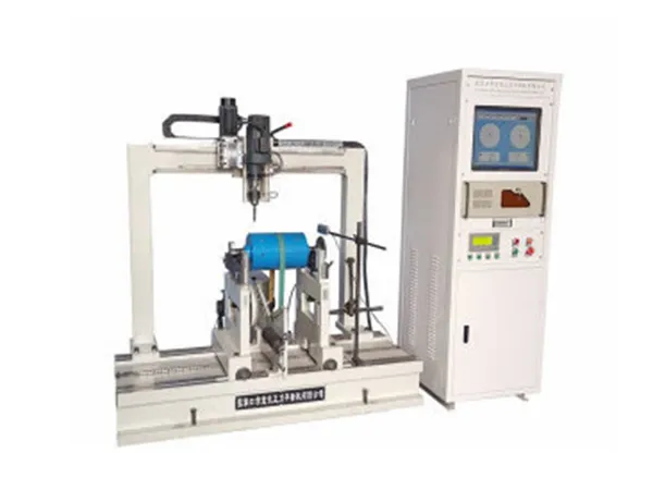
Features
- The drive motor uses a flat belt placed at the rotor’s center to keep rotation smooth and stable during testing.
- An integrated drilling unit, controlled by PLC, moves across an 800 mm range on the beam with a 20 mm drill bit to perform unbalance correction directly above the workpiece.
- Once measurement is complete, the drill automatically stops at the correction point, removing material on both balancing planes.
- Drill depth is calculated after selecting the bit diameter and the density of the material, improving correction accuracy.
- A printer is included for generating A4 reports of the test results.
- An industrial vacuum system is provided to collect chips from the drilling process, keeping the workspace clean.
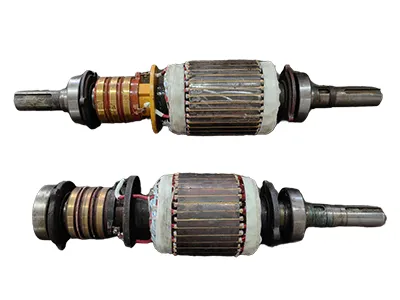 Electric motor rotor balancing
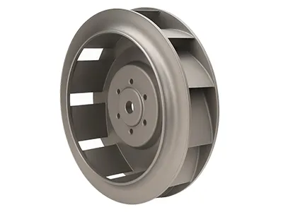 Impellers balancing
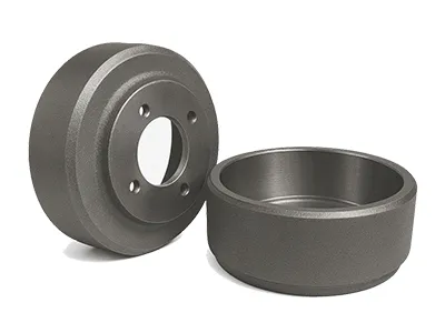 Brake drums balancing
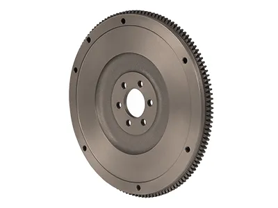 Flywheels balancing